 en
en русский
 Español
 عربى
عربى
Membrane Helium Recovery Unit: Advanced Recovery, Purification, and Closed-Loop Gas Reuse
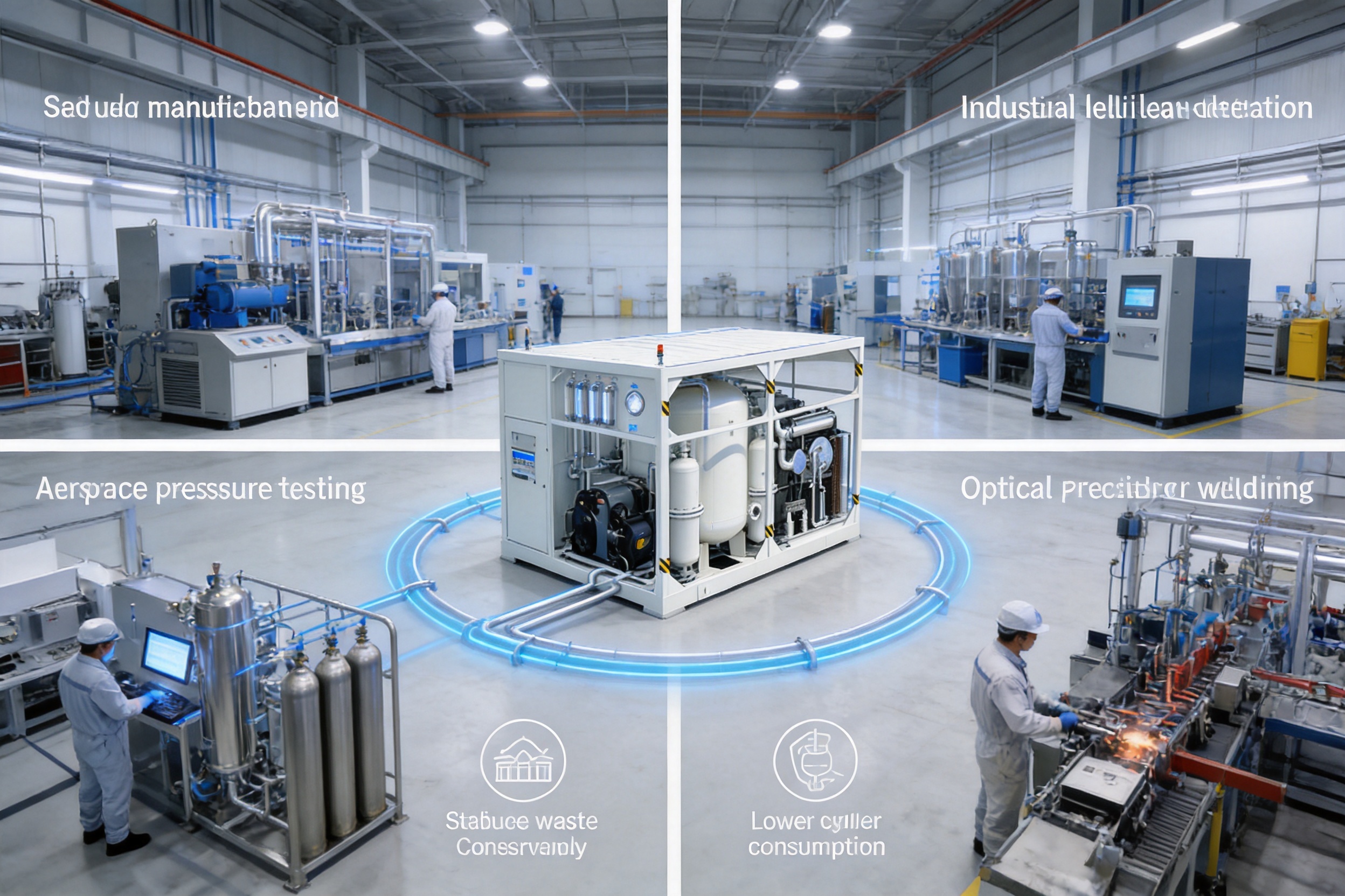
Helium is one of the most valuable industrial gases because of its unique physical and chemical properties. It is inert, lightweight, highly permeable, nonflammable, and capable of maintaining performance under extreme temperature conditions. These characteristics make helium indispensable in semiconductor manufacturing, medical superconducting systems, aerospace testing, optical fiber production, precision welding, scientific research, and industrial leak detection.
However, helium is also a non-renewable strategic resource. Most industrial users depend on external helium supplies, while traditional operating methods often release large quantities of helium after a single use. In many leak detection, welding, testing, and manufacturing processes, helium becomes mixed with air, water vapor, oil mist, dust, and other contaminants before being discharged. Although the concentration may be too low for direct reuse, the gas still contains considerable recoverable helium.
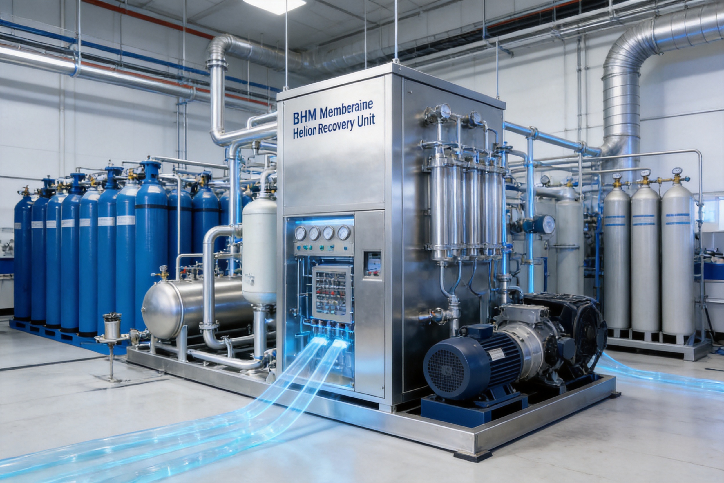
The BHM Membrane Helium Recovery Unit is designed to solve this problem. It applies ambient-temperature membrane separation, graded pretreatment, online monitoring, compression, storage, and closed-loop reuse to recover helium from mixed process exhaust. The system is designed to enrich and purify helium while reducing dependence on virgin helium cylinders or liquid helium deliveries.
Compared with conventional venting, the recovery unit can reduce helium waste and improve supply stability. Compared with adsorption-based purification, it avoids routine adsorbent regeneration. Compared with cryogenic recovery, it can operate without a complete low-temperature separation train for applications where high-pressure gaseous helium is sufficient. The modular design also allows the system to be configured for different gas flow rates, helium concentrations, impurity profiles, and final purity requirements.
BHM Membrane Helium Recovery Unit
Content
- 1 1. The Industrial Need for Helium Recovery
- 2 2. Product Overview
- 3 3. How Membrane Helium Separation Works
- 4 4. Complete Process Flow
- 4.1 4.1 Waste Gas Collection
- 4.2 4.2 Pressure Stabilization and Buffering
- 4.3 4.3 Dust and Oil Removal
- 4.4 4.4 Drying and Moisture Control
- 4.5 4.5 Primary Membrane Enrichment
- 4.6 4.6 Secondary Membrane Purification
- 4.7 4.7 Fine Purification and Polishing
- 4.8 4.8 Online Detection
- 4.9 4.9 Compression and Storage
- 5 5. Main Product Advantages
- 6 6. Comparison with Competing Technologies
- 7 7. Application-Specific Solutions
- 8 8. Intelligent Control and Safety Features
- 9 9. Manufacturing and Engineering Strengths
- 10 10. Operation and Maintenance
- 11 11. Project Design and Selection Guidelines
- 12 12. Economic and Environmental Benefits
- 13 13. Frequently Asked Questions
- 13.1 Q1. What type of gas can the unit process?
- 13.2 Q2. Does the system use chemical reactions?
- 13.3 Q3. Does the membrane process require cryogenic temperatures?
- 13.4 Q4. Can the unit recover helium from leak detection exhaust?
- 13.5 Q5. Can the unit produce 5N or 6N helium?
- 13.6 Q6. What happens if the recovered gas is off specification?
- 13.7 Q7. Is the system suitable for continuous operation?
- 13.8 Q8. Can it handle intermittent gas discharge?
- 13.9 Q9. How often do the membranes need to be replaced?
- 13.10 Q10. Can the unit be expanded later?
- 13.11 Q11. Is liquid helium produced directly by the membrane unit?
- 13.12 Q12. What information is required for a quotation?
- 14 14. Conclusion
- 15 References
- 16 Product: BHM Membrane Helium Recovery Unit
1. The Industrial Need for Helium Recovery
Helium is widely used in processes where ordinary gases cannot provide the same combination of inertness, thermal performance, permeability, and chemical stability. Its applications include mass spectrometer leak testing, semiconductor equipment cooling, wafer processing, superconducting magnet systems, rocket and spacecraft testing, optical fiber preform production, high-end welding, and specialized laboratory equipment.
In many of these applications, helium is not chemically consumed. Instead, it leaves the process as a tail gas. This creates an important opportunity: if the discharged gas can be collected, purified, and returned to the process, the same helium can be used repeatedly.
Conventional helium management often follows a simple linear pattern. Purchased helium enters the production process, performs its function, mixes with air or other impurities, and is vented. This method is easy to operate, but it creates several disadvantages:
High consumption of purchased helium.
Exposure to international helium price fluctuations.
Potential production interruptions when supply is delayed.
Loss of a non-renewable strategic resource.
Increased operating costs caused by frequent cylinder or liquid helium replenishment.
Limited visibility into helium recovery efficiency and process losses.
The need for recovery is especially strong in industrial leak detection. After a test, the residual helium is commonly diluted with a large volume of air. The resulting mixture may contain moisture, oil vapor, dust, and process contaminants. Direct reuse is normally impossible without purification, but the helium concentration may still be high enough for an engineered recovery system.
Continuous applications create another type of loss. Optical fiber manufacturing and precision welding can discharge helium steadily over long periods. Even when the instantaneous flow is moderate, annual helium loss can become substantial. A recovery system connected to the production line can collect this gas continuously and return purified helium to the process.
High-purity applications create a different challenge. Semiconductor and scientific research processes may require 5N or 6N helium, depending on the equipment and process specification. These applications demand careful control of moisture, oxygen, hydrocarbons, particles, and other trace impurities. The recovery system must therefore combine membrane separation with suitable polishing, drying, detection, and recirculation steps.
2. Product Overview
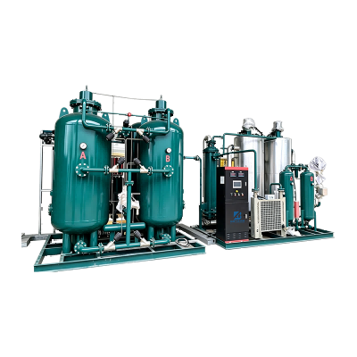
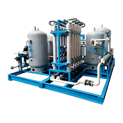
The BHM Membrane Helium Recovery Unit is an integrated gas recovery and purification system for mixed helium exhaust. It is built around polymeric hollow-fiber membrane modules and supported by collection, pretreatment, pressure stabilization, fine purification, analysis, compression, storage, and control equipment.
The primary purpose of the unit is to separate fast-permeating helium from slower-permeating gases and contaminants. The separation takes place at approximately ambient temperature and is driven by a difference in gas partial pressure across the membrane. Helium preferentially dissolves into and diffuses through the selective membrane layer, while much of the nitrogen, oxygen, carbon dioxide, water, oil-related contaminants, and particulate matter remains on the feed or retentate side.
The recovered helium-rich stream can then pass through additional membrane stages and fine purification equipment. After online confirmation of purity, the gas is compressed and stored for reuse. Gas that does not meet the specified quality requirement can be returned to the purification loop instead of being sent directly to the production process.
The system can be configured for several operating modes:
High-pressure gaseous helium recovery for industrial testing and manufacturing.
Continuous closed-loop helium supply for optical fiber and welding lines.
High-purity recovery for semiconductor and research applications.
Intermittent recovery for aerospace tests and maintenance operations.
Pre-purification for subsequent liquefaction in specialized medical or scientific installations.
The final configuration depends on feed gas composition, helium concentration, flow rate, pressure, desired product purity, recovery target, storage pressure, and the customer’s process interface. As a result, the unit is not simply a standard filter. It is an engineered gas recovery platform designed around the operating conditions of each facility.
3. How Membrane Helium Separation Works
3.1 Solution-Diffusion Separation
The membrane operates through a solution-diffusion mechanism. Gas molecules first contact the selective membrane surface, dissolve into the membrane material, diffuse through the polymer matrix, and desorb on the opposite side. Different gases move through the membrane at different rates because their size, solubility, diffusivity, and interaction with the polymer are different.
Helium has an extremely small kinetic diameter, approximately 0.20 nanometers, and a high ability to permeate suitable polymer membranes. When a pressure or partial-pressure difference is maintained across the membrane, helium moves rapidly toward the permeate side. Larger or less-permeable components remain preferentially in the retentate stream.
The process does not depend on a chemical reaction. It does not consume helium through conversion, and it does not require helium to undergo a phase change. This makes the method attractive for applications where the objective is to recover the same gas for reuse.
3.2 Selective Permeation
In a typical membrane module, the mixed waste gas enters the feed side at a controlled pressure. Helium selectively permeates through the hollow fibers and becomes enriched in the permeate stream. The remaining gas leaves the module as retentate containing a higher proportion of the slower gases.
One membrane stage may not be sufficient to achieve the final product specification. For this reason, the BHM system can use multiple membrane stages in series or parallel. Series stages provide progressive enrichment and purification, while parallel modules increase capacity for larger flow rates.
A typical gas permeation tendency used in the system design is:
He > H₂ > O₂ > N₂ > H₂O > oil and other heavy contaminants
This ranking is a design reference rather than a universal value for every membrane material and operating condition. Actual separation performance depends on membrane composition, pressure, temperature, feed composition, humidity, contamination, stage cut, and module configuration. Baiao’s engineering approach is therefore based on process-specific design rather than on a single theoretical separation factor.
3.3 Pressure Difference as the Driving Force
Membrane separation requires a suitable driving force. This force is normally created through feed-side pressure, permeate-side pressure reduction, or a combination of both. The pressure difference determines the rate at which helium passes through the membrane and affects the balance between product recovery and product purity.
Higher recovery and higher purity may require different operating conditions. For example, maximizing recovery may allow more helium to remain in the retentate, while maximizing purity may require additional stages or lower throughput. The control system therefore regulates pressure, flow, temperature, and stage operation to match the required product specification.
Pressure stabilization is particularly important when the waste gas is generated intermittently. Buffer tanks and controlled collection systems help prevent sudden flow changes from causing membrane overload, unstable purity, or unnecessary venting.
4. Complete Process Flow
The BHM Membrane Helium Recovery Unit uses an integrated process architecture:
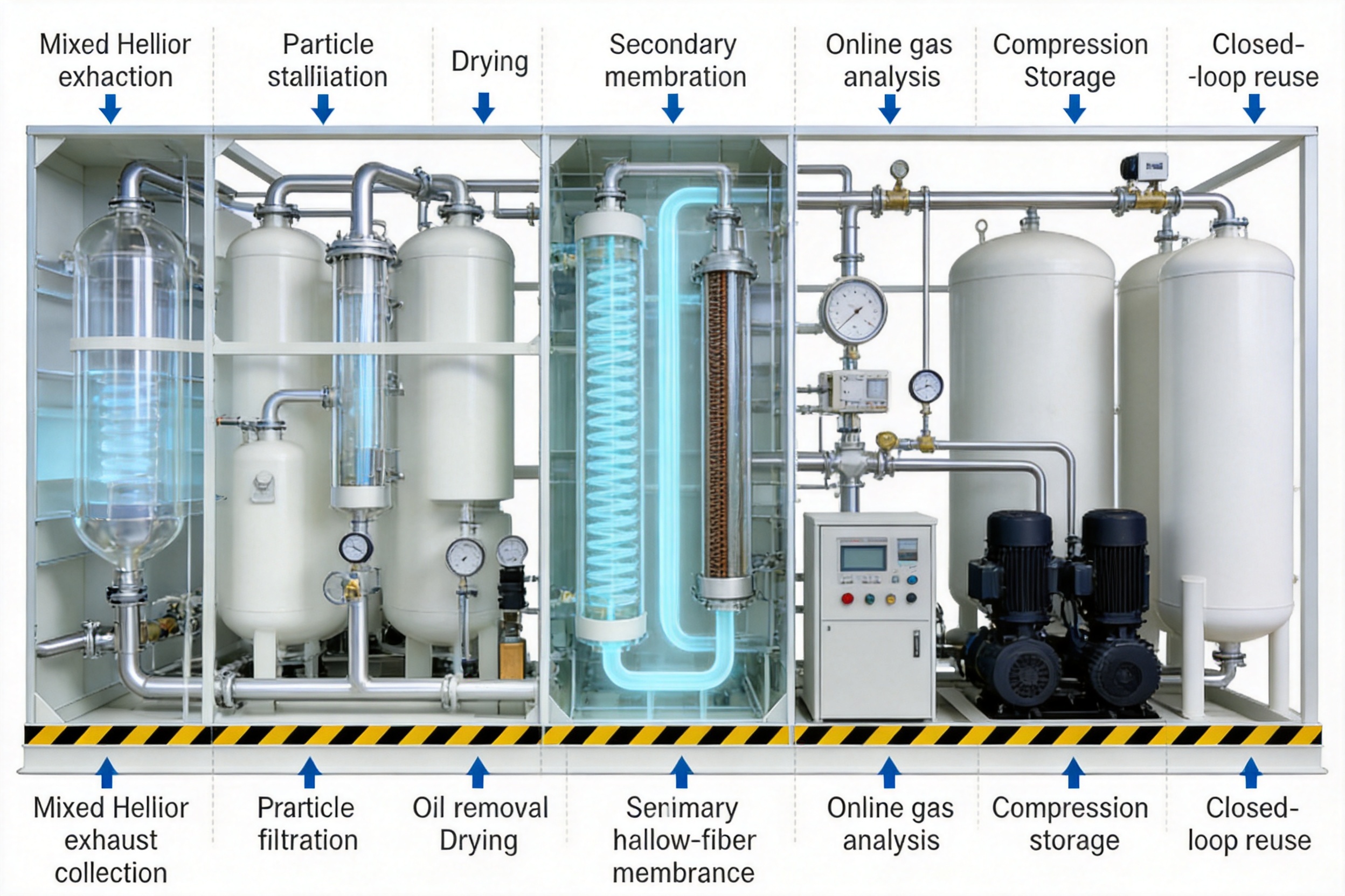
Waste Gas Collection → Pressure Stabilization → Coarse Filtration → Oil Removal → Drying → Primary Membrane Separation → Secondary Membrane Purification → Fine Treatment → Online Analysis → Compression → Storage → Closed-Loop Reuse
4.1 Waste Gas Collection
The first stage is the controlled collection of helium-containing exhaust. Collection quality directly affects overall recovery. If helium escapes into the workshop instead of entering the recovery pipeline, it cannot be recovered efficiently.
For continuous processes, the system can use sealed stainless steel pipelines connected directly to process equipment. Negative-pressure collection helps reduce unorganized emissions and can improve collection efficiency. For intermittent applications, flexible hoods, local extraction points, and buffer tanks can be used to capture gas released during testing or maintenance.
Collection pipelines are selected according to pressure, flow, cleanliness, corrosion resistance, and helium leakage requirements. Stainless steel seamless tubing is commonly used where low contamination and low permeability are important. Proper connection design, welding quality, valve selection, and leak testing are essential to prevent loss before the gas reaches the purification equipment.
4.2 Pressure Stabilization and Buffering
Helium exhaust may be produced at irregular intervals. A buffer vessel absorbs flow fluctuations and protects downstream membrane modules from abrupt pressure changes. The stabilization unit can also separate collection events from purification operation, allowing the membrane system to operate closer to its design point.
For high-pressure aerospace or industrial testing, the buffer system must be selected for the maximum working pressure, instantaneous discharge volume, and applicable safety requirements. For low-pressure leak detection exhaust, the equipment may focus more on negative-pressure collection and controlled compression.
4.3 Dust and Oil Removal
Particles and oil aerosols can damage or foul membrane elements. The pretreatment section therefore normally includes a primary particle filter and a precision coalescing or oil-removal filter. These devices remove dust, droplets, aerosolized oil, and other suspended substances before the gas contacts the selective membrane.
In aerospace, automotive, and industrial leak detection applications, the exhaust may contain residues from lubricants, test components, vacuum pumps, or workshop environments. Pretreatment protects the membrane, reduces maintenance requirements, and supports stable long-term performance.
4.4 Drying and Moisture Control
Water vapor can affect membrane performance, downstream analyzers, compression equipment, and final gas quality. The system can include a drying tower, refrigerated dryer, or other moisture-control equipment selected according to the feed conditions and target specification.
For high-purity output, moisture removal is combined with online trace moisture measurement. The design objective may be to reduce water vapor to a low parts-per-million level before final delivery, with the exact requirement determined by the customer’s process standard.
4.5 Primary Membrane Enrichment
The pretreated gas enters the first membrane stage. This stage performs bulk separation and initial helium enrichment. Most of the helium passes preferentially through the membrane, while the major fraction of air and other slower gases remains in the retentate.
The primary stage is designed to handle the largest impurity load. Its purpose is not necessarily to achieve the final purity in one pass. Instead, it reduces the volume and impurity burden for the downstream stages.
4.6 Secondary Membrane Purification
The enriched helium stream can pass through one or more additional membrane stages. These stages improve helium concentration and reduce residual nitrogen, oxygen, and other gaseous contaminants. Two-stage membrane arrangements are commonly suited to industrial recovery applications requiring high-purity helium, while three-stage systems can be combined with trace impurity treatment for more demanding applications.
Membrane modules may be installed in series, parallel, or a combination of both. Series installation increases purification depth. Parallel installation increases processing capacity and can provide operational redundancy. Modular expansion allows users to add capacity as production increases.
4.7 Fine Purification and Polishing
Membrane separation is the core technology, but some applications require additional treatment. Trace deoxidation, final drying, hydrocarbon removal, particle filtration, or other polishing steps may be installed after membrane separation.
This hybrid arrangement is particularly useful for semiconductor, medical research, and scientific applications. The membrane stage performs the main gas separation efficiently, while the polishing unit addresses trace impurities that must be controlled to very low levels.
4.8 Online Detection
Online analysis provides continuous information about helium purity and critical contaminants. Depending on the application, the system can include gas chromatography, oxygen analyzers, moisture analyzers, pressure transmitters, flowmeters, and other instruments.
If the product meets the programmed specification, it is sent to the compressor and storage system. If the gas is outside specification, an automatic valve can redirect it for additional purification. This approach prevents off-specification gas from entering sensitive production equipment.
4.9 Compression and Storage
After purification, the recovered helium is compressed to the pressure required by the reuse process. High-pressure storage tanks provide a stable supply during fluctuations in production demand.
For industrial leak detection, welding, and manufacturing, high-pressure gaseous storage is often the most practical choice. For medical superconducting and research applications, the recovery system may be integrated with a helium re-liquefaction system and cryogenic storage equipment where appropriate. Liquefaction is not a direct function of the membrane module itself; it is a downstream process selected for applications that require liquid helium.
5. Main Product Advantages
5.1 Ambient-Temperature Operation
The BHM unit uses membrane separation at near-ambient operating temperature. Unlike cryogenic distillation, the core separation does not require a low-temperature phase-change process. This reduces the need for large refrigeration systems and simplifies start-up and shutdown procedures.
Ambient-temperature operation is also advantageous for facilities that have limited space, limited utilities, or a need for rapid response. The system can be integrated into an existing production area without building a complete cryogenic plant.
5.2 No Routine Adsorbent Regeneration
PSA systems depend on adsorbent beds and repeated pressurization and depressurization cycles. Adsorbents may gradually age, become contaminated, or require replacement. Valve switching and regeneration also create a more complex operating sequence.
The membrane process does not use cyclic adsorbent regeneration for its primary separation function. This can reduce valve switching, simplify control logic, and lower the quantity of consumable purification media. Filters and auxiliary treatment components still require inspection and replacement, but the central membrane separation mechanism is continuous rather than cyclic.
5.3 Lower Mechanical Complexity Than Cryogenic Systems
Cryogenic helium recovery and liquefaction can provide excellent performance, but they require specialized refrigeration, vacuum insulation, cryogenic vessels, and strict low-temperature controls. Such systems may be justified for large-volume liquid helium operations, but they can be excessive for gaseous helium recovery in industrial testing or manufacturing.
The membrane-based unit offers a more compact alternative when the required product is high-pressure gas or when membrane purification is used as a front-end process before liquefaction.
5.4 Modular Capacity
Membrane modules can be arranged to match the customer’s flow rate. Small systems can serve intermittent leak detection or laboratory applications, while larger systems can use multiple modules in parallel for continuous production.
Modularity offers practical advantages during expansion. A customer may begin with a recovery system for one production line and add modules when more equipment is connected. This avoids the need to oversize the original system or replace the complete unit during future growth.
5.5 Rapid Start-Up and Flexible Operation
Membrane equipment generally reaches operating conditions faster than a large cryogenic plant. This is useful for batch production, aerospace testing, maintenance operations, and facilities with changing schedules.
Control parameters can be adjusted for different feed compositions, flow rates, and purity targets. The system can also operate in automatic, semi-automatic, or manual modes depending on the plant control philosophy.
5.6 Protection Against Supply Disruption
Recovering helium on-site does not eliminate the need for make-up helium in every application, but it can substantially reduce the quantity purchased. This creates a buffer against price fluctuations, transportation delays, cylinder shortages, and international supply disruptions.
A closed-loop system also provides greater control over gas quality. Rather than relying entirely on external supply, the customer can monitor the quality of recovered helium before returning it to the process.
5.7 Reduced Environmental Waste
Helium recovery conserves a finite resource and reduces the energy and logistics associated with producing, transporting, and delivering replacement helium. Although the recovery system consumes electricity for fans, compressors, dryers, analyzers, and controls, the overall resource efficiency can be significantly improved when the recovered gas displaces large quantities of purchased helium.
6. Comparison with Competing Technologies
Technology |
Main Principle |
Advantages |
Limitations |
Role of the BHM System |
Membrane separation |
Selective dissolution and diffusion through a membrane |
Ambient-temperature operation, compact design, continuous processing, modular capacity |
Performance depends on feed composition and requires suitable pretreatment |
Core recovery and enrichment technology |
PSA adsorption |
Selective adsorption and cyclic regeneration |
Useful for many gas purification duties and adaptable to certain high-purity applications |
Requires adsorbent beds, valve switching, regeneration, and consumable management |
Membrane separation can reduce dependence on cyclic adsorption for the main recovery stage |
Cryogenic distillation |
Low-temperature phase separation |
Suitable for large-scale, high-purity gas processing and liquid product generation |
High capital cost, complex refrigeration, long start-up, and high energy demand |
Membrane recovery can serve as an independent process or front-end concentration stage |
Direct venting |
No recovery |
Simple installation and minimal equipment |
Maximum helium loss and no protection against supply or price risks |
The recovery unit replaces wasteful one-way discharge with closed-loop reuse |
The appropriate technology depends on the customer’s required flow rate, purity, pressure, product state, and economic conditions. Membrane separation is especially attractive when the gas is diluted, the process is continuous or intermittent, the customer requires gaseous helium, and compact equipment with low maintenance is preferred.
For very large facilities requiring liquid helium production, membrane recovery may be combined with compression and liquefaction. In this configuration, the membrane system reduces the impurity load and concentrates helium before the cryogenic section, potentially improving the overall process arrangement.
7. Application-Specific Solutions
7.1 Semiconductor Manufacturing
Semiconductor production requires strict control of particles, moisture, oxygen, hydrocarbons, and other impurities. Helium may be used for cooling, equipment protection, purging, leak detection, and specialized process operations.
The recommended process includes sealed collection, high-efficiency particle filtration, drying, multi-stage membrane separation, trace impurity polishing, precision analysis, compression, and closed-loop return. A three-stage membrane arrangement with fine treatment can be selected when 6N-class helium is required, subject to validation against the customer’s process specification.
Because semiconductor facilities operate continuously and consume high-value gases, even a moderate recovery percentage can create significant annual savings. The system can be connected to selected tools or to a centralized gas collection network. Segregating gas streams by impurity profile may improve purification efficiency and protect the cleanest gas from contamination.
7.2 Medical MRI and Superconducting Research
Superconducting magnets and scientific systems use helium for cryogenic cooling. Helium losses can occur through boil-off, maintenance venting, pressure relief, and service operations.
These applications require particularly careful control of contamination and moisture. The recovery system can collect gaseous helium, stabilize the pressure, remove particles and moisture, purify the stream, and direct it toward compression or re-liquefaction. Where liquid helium is required, the membrane unit serves as part of a larger recovery and liquefaction system.
The recovery rate depends on the equipment design, gas collection efficiency, operating schedule, and quantity of helium lost through unavoidable leakage. Proper cryogenic engineering and safety procedures remain essential.
7.3 Industrial Leak Detection
Industrial leak detection is one of the most suitable applications for helium recovery. Test gas commonly mixes with a substantial amount of air after the inspection. The discharged stream may contain changing helium concentrations, humidity, pump oil, and workshop contaminants.
A flexible negative-pressure collection system can capture exhaust from test stations. Oil and water removal protects the membranes, while staged membrane separation enriches the helium. Online detection determines whether the recovered gas is ready for reuse or should be returned for further treatment.
For many industrial leak detection systems, a double-stage membrane arrangement with suitable polishing can be designed for 5N-class helium output. The actual specification must be confirmed by analyzing the feed gas and validating the recovered gas under operating conditions.
7.4 Aerospace and Defense Testing
Aerospace systems use helium for pressure testing, purging, propulsion system preparation, cryogenic testing, and component evaluation. These operations may generate short-duration, high-volume discharges at elevated pressure.
The recovery system for aerospace testing requires a high-pressure buffer, pressure-rated valves, suitable filtration, controlled decompression, and carefully designed safety functions. If fuel residues or other flammable contaminants may be present, the collection and treatment equipment must be selected according to the applicable hazardous-area classification.
Membrane modules can recover helium after the pressure and impurity profile have been stabilized. High-pressure storage allows the recovered gas to be reused during subsequent test cycles.
7.5 Optical Fiber Production
Helium can be used as a carrier or process gas during optical fiber preform production. The process may generate a continuous exhaust stream containing helium, air, moisture, and oxidation-related impurities.
A sealed collection pipeline connected to the production line can deliver the gas to filters, dryers, membrane modules, analyzers, and a return compressor. Because this process operates continuously, the recovery system can be sized for a stable flow and optimized for long-term energy efficiency.
7.6 Precision Welding
Helium shielding gas is used in specialized welding applications where high heat input, arc characteristics, or protection against oxidation are important. Exhaust gas may contain air, moisture, metal fumes, oil vapor, and other workshop contaminants.
Effective particle filtration and moisture control are essential before membrane treatment. The recovered helium can be purified and blended or returned to the welding supply system when it meets the required quality standard.
8. Intelligent Control and Safety Features
The BHM unit uses PLC-based control to coordinate collection, pressure stabilization, membrane operation, drying, analysis, compression, storage, and emergency functions. Key variables may include feed pressure, permeate pressure, flow rate, temperature, oxygen concentration, moisture concentration, helium purity, compressor status, and tank pressure.
Automatic control can provide the following functions:
Adjustment of collection negative pressure.
Control of membrane feed pressure and flow distribution.
Automatic start-up and shutdown sequences.
Automatic diversion of off-specification gas.
High-pressure and low-pressure alarms.
Analyzer fault indication and calibration reminders.
Compressor overload protection.
Leakage and abnormal purity alarms.
Emergency isolation and bypass operation.
Historical data recording for production and maintenance analysis.
Helium is inert and nonflammable, but a high concentration in an enclosed space can displace oxygen. The installation should therefore include suitable ventilation and oxygen-deficiency monitoring. Pressure vessels, pipelines, valves, and compressors must be selected and tested according to the applicable pressure and industrial safety regulations.
Where the recovered gas may contain fuel residues, oil vapor, or other flammable substances, explosion protection, grounding, electrical classification, and gas detection must be evaluated. The system should include a safe emergency venting route so that abnormal gas can be isolated without creating an unsafe pressure condition.
9. Manufacturing and Engineering Strengths
Zhejiang Baiao Gas Equipment Co., Ltd. is a gas equipment manufacturer based in Hangzhou, China. The company integrates research and development, process design, equipment manufacturing, installation, commissioning, and after-sales service.
The company operates a standardized production workshop, office facilities, and warehouse resources that support equipment assembly, component management, project coordination, and service delivery. Its technical scope covers gas separation and purification equipment, including PSA nitrogen generators, PSA oxygen generators, membrane gas generators, nitrogen purification units, ammonia decomposition hydrogen purification equipment, and customized industrial gas systems.
This broader experience is important for helium recovery because a complete recovery plant involves more than membrane modules. It requires expertise in gas collection, filtration, drying, pressure regulation, compression, storage, instrumentation, automation, and customer-site integration.
The company’s manufacturing and engineering strengths include:
Integrated design and production capability for gas separation equipment.
Experience with industrial gas purification and process integration.
Modular equipment design for different flow rates and applications.
Selection of localized components and membrane technologies suited to industrial conditions.
Factory assembly and pre-delivery inspection before shipment.
Installation, commissioning, operator training, and after-sales support.
Customization according to pressure, purity, flow, impurity, and site requirements.
Quality control begins with engineering specifications. The membrane type, module quantity, filter grade, dryer capacity, compressor rating, instrumentation range, and storage volume should all be selected from process data rather than estimated only from nominal gas consumption.
During manufacturing, piping arrangement, valve accessibility, instrument installation, electrical wiring, skid structure, and maintenance clearance must be reviewed. Factory inspection can include pressure testing, leak testing, instrument verification, control logic testing, alarm testing, and simulated operating sequences.
At the customer site, commissioning should verify the actual gas composition, flow rate, operating pressure, humidity, oil content, recovery rate, product purity, and storage performance. This site validation helps confirm that the installed system matches the design basis.
10. Operation and Maintenance
Routine maintenance is necessary to protect membrane performance and preserve recovery efficiency. The recommended maintenance schedule depends on feed gas cleanliness and operating hours, but several practices are generally important.
10.1 Daily Inspection
Operators should review pipeline pressure, membrane inlet conditions, permeate flow, retentate flow, product purity, moisture readings, oxygen readings, compressor status, and storage pressure. Any sudden change may indicate a filter blockage, valve problem, leak, analyzer fault, or membrane performance issue.
10.2 Filter Management
Filters should be inspected according to differential pressure and operating time. A heavily loaded filter can reduce flow and increase energy consumption. Oil-removal elements should be replaced before contamination reaches the membrane modules.
10.3 Dryer and Moisture Control
Drying equipment should be checked for capacity, regeneration or drainage performance, and outlet moisture. The dryer must be sized for the actual water load rather than only the nominal gas flow.
10.4 Analyzer Calibration
Online oxygen, moisture, and purity analyzers should be calibrated at scheduled intervals. Calibration records should be maintained because product release decisions depend on reliable measurement.
10.5 Compressor and Storage Inspection
Boosters and compressors require lubrication, cooling, vibration, seal, and pressure checks in accordance with the manufacturer’s instructions. Storage vessels, safety valves, pressure gauges, and isolation valves should be inspected under the applicable pressure equipment regulations.
10.6 Membrane Protection
Membranes should be protected from liquid carryover, excessive oil contamination, particles, chemical vapors, and inappropriate pressure or temperature conditions. Good pretreatment and stable operation generally provide better membrane life than repeated operation under severe contamination conditions.
11. Project Design and Selection Guidelines
A successful helium recovery project begins with accurate process information. Before equipment selection, the customer should provide the following data:
Helium concentration range in the waste gas.
Minimum, normal, and maximum gas flow rate.
Feed pressure and temperature.
Moisture, oxygen, nitrogen, carbon dioxide, oil, and particle content.
Operating schedule and batch or continuous characteristics.
Required product purity.
Required storage pressure and reuse pressure.
Whether the final product is gaseous or must be liquefied.
Available power, cooling water, compressed air, drainage, and ventilation.
Site classification and applicable safety standards.
The expected recovery rate should be calculated from the entire system, not only the membrane module. Collection efficiency, pipeline leakage, pretreatment losses, membrane stage cut, off-specification recycle, compressor performance, and unavoidable venting all affect the final result.
Likewise, product purity should be verified at the point of reuse. A gas may be highly enriched in helium but still require additional treatment if the application has strict moisture or oxygen limits. The system should therefore be designed around the complete product specification.
12. Economic and Environmental Benefits
The economic value of helium recovery is primarily linked to avoided helium purchases. The actual payback period depends on helium price, annual consumption, operating hours, gas loss, recovery rate, electricity cost, maintenance cost, and system investment.
Facilities with high helium consumption and frequent direct venting usually have the strongest business case. Industrial leak detection workshops, semiconductor facilities, optical fiber production plants, and large research or medical installations may achieve substantial reductions in virgin helium demand.
The economic analysis should include:
Current annual helium purchases.
Expected recoverable helium quantity.
Make-up helium required after installation.
Electricity consumption of the recovery system.
Filter, dryer, analyzer, and compressor maintenance.
Operator and service costs.
Production benefits from improved supply stability.
Potential cost of production interruptions caused by helium shortages.
In addition to direct savings, closed-loop operation reduces exposure to supply chain volatility. The customer can maintain a reserve of recovered helium and use purchased helium mainly as make-up gas rather than as the sole source of supply.
From an environmental perspective, recycling helps conserve a non-renewable resource. It can also reduce the transportation, packaging, and handling associated with repeated helium deliveries. The system’s electricity consumption should be evaluated as part of a complete life-cycle assessment, but in many applications the avoided resource consumption is the dominant benefit.
13. Frequently Asked Questions
Q1. What type of gas can the unit process?
The unit is designed for helium-containing waste gas mixed with air and other impurities. Depending on the project, the feed may contain nitrogen, oxygen, water vapor, carbon dioxide, oil vapor, particles, and trace process contaminants. The exact pretreatment design must be based on a gas analysis.
Q2. Does the system use chemical reactions?
The core membrane separation process is physical. Helium is separated through selective permeation rather than chemical conversion. Additional polishing equipment, such as catalytic deoxidation, may use a separate treatment principle when required by the final purity specification.
Q3. Does the membrane process require cryogenic temperatures?
No. The membrane separation stage operates at approximately ambient temperature. Cryogenic equipment may be added downstream if the customer needs helium liquefaction, but it is not required for ordinary high-pressure gaseous helium recovery.
Q4. Can the unit recover helium from leak detection exhaust?
Yes. Industrial leak detection is a major application. The system can collect diluted helium exhaust, remove oil, water, and particles, enrich helium through multiple membrane stages, verify product purity, and store the recovered gas for reuse.
Q5. Can the unit produce 5N or 6N helium?
The configured system can be designed for high-purity helium output, with two-stage membrane separation commonly considered for 5N-class applications and additional membrane stages or fine treatment used for more demanding specifications. Final purity depends on feed composition, pretreatment, membrane configuration, polishing equipment, and validation testing.
Q6. What happens if the recovered gas is off specification?
Online analyzers can identify off-specification gas. The control system can automatically redirect it to the purification loop or a designated safe outlet instead of sending it to the production process.
Q7. Is the system suitable for continuous operation?
Yes. The modular membrane system, automated control, online monitoring, and appropriate pretreatment allow continuous operation. Equipment capacity and redundancy should be selected according to the customer’s production schedule and maintenance philosophy.
Q8. Can it handle intermittent gas discharge?
Yes. Buffer tanks and pressure stabilization equipment can be used to manage batch or intermittent discharge. This arrangement allows the purification section to operate at a more stable flow rate.
Q9. How often do the membranes need to be replaced?
Membrane service life depends on operating pressure, temperature, contamination, moisture, oil exposure, cleaning practices, and operating hours. Good pretreatment and proper operating control help extend membrane life. Filters and auxiliary consumables generally require more frequent maintenance than the membrane modules.
Q10. Can the unit be expanded later?
Yes. Parallel membrane modules, additional compression capacity, expanded storage, or upgraded pretreatment can be incorporated when the customer’s gas volume increases. Expansion is easier when the original system includes suitable pipe headers, control capacity, and space allowances.
Q11. Is liquid helium produced directly by the membrane unit?
No. The membrane unit recovers and purifies helium gas. If liquid helium is required, the purified gas must be sent to a compatible re-liquefaction system. The membrane unit can serve as the recovery and pre-purification section of that larger system.
Q12. What information is required for a quotation?
The supplier normally requires gas composition, flow range, pressure, temperature, impurity profile, target purity, storage pressure, operating schedule, installation environment, utility conditions, and the intended reuse point.
14. Conclusion
The BHM Membrane Helium Recovery Unit provides an efficient approach to recovering helium from industrial exhaust and returning it to productive use. Its core membrane technology uses selective permeation at ambient temperature, while integrated filtration, drying, staged purification, online analysis, compression, and storage create a complete closed-loop solution.
The system offers important advantages over direct venting, including lower helium consumption, improved supply stability, reduced resource waste, and better control of recovered gas quality. Compared with PSA-centered systems, it avoids routine adsorbent regeneration in the core separation stage. Compared with cryogenic systems, it provides a simpler and more compact option for gaseous helium recovery and can also function as a front-end concentration process for liquefaction.
The product is suitable for industrial leak detection, semiconductor manufacturing, superconducting research, aerospace testing, optical fiber production, precision welding, and other applications where helium is valuable but currently discharged after use.
Its performance depends on proper engineering. Collection efficiency, pretreatment, membrane staging, pressure control, final polishing, online detection, and storage must all be matched to the customer’s process. With appropriate design and operation, the recovery unit can support a long-term transition from one-way helium consumption to controlled, measurable, and economically efficient gas circulation.
Zhejiang Baiao Gas Equipment Co., Ltd. supports this type of project through gas separation expertise, equipment manufacturing, system integration, installation, commissioning, and after-sales service. Its wider experience in industrial gas generation and purification provides a foundation for developing customized helium recovery systems suited to different production environments and purity requirements.
References
1. Baker, R. W. Membrane Technology and Applications. Industrial membrane separation principles and process design.
2. Mulder, M. Basic Principles of Membrane Technology. Fundamentals of solution-diffusion transport and selective permeation.
3. International Organization for Standardization. Gas quality, compressed gas handling, and industrial gas safety standards.
4. Compressed Gas Association. Guidance for the handling, storage, and distribution of helium and other compressed gases.
5. Perry’s Chemical Engineers’ Handbook. Gas separation, filtration, drying, compression, and process equipment design references.
6. Industrial gas recovery engineering practice. Principles for waste gas collection, pressure stabilization, purification, online analysis, and closed-loop reuse.
7. Cryogenic engineering practice. General design considerations for helium recovery, re-liquefaction, storage, and superconducting applications.
Product: BHM Membrane Helium Recovery Unit

- Tel: +86-15057127179
+86-13588382771 - Email: huang.yifan0215@gmail.com
- Address: Huanshan Township, Fuyang District, Hangzhou City, Zhejiang Province
Copyright © Zhejiang Baiao Gas Equipment Co., Ltd. All Rights Reserved.
Privacy
Gas Generator Plant Manufacturer, Industrial Purification Equipment Plant
