 en
en русский
 Español
 عربى
عربى
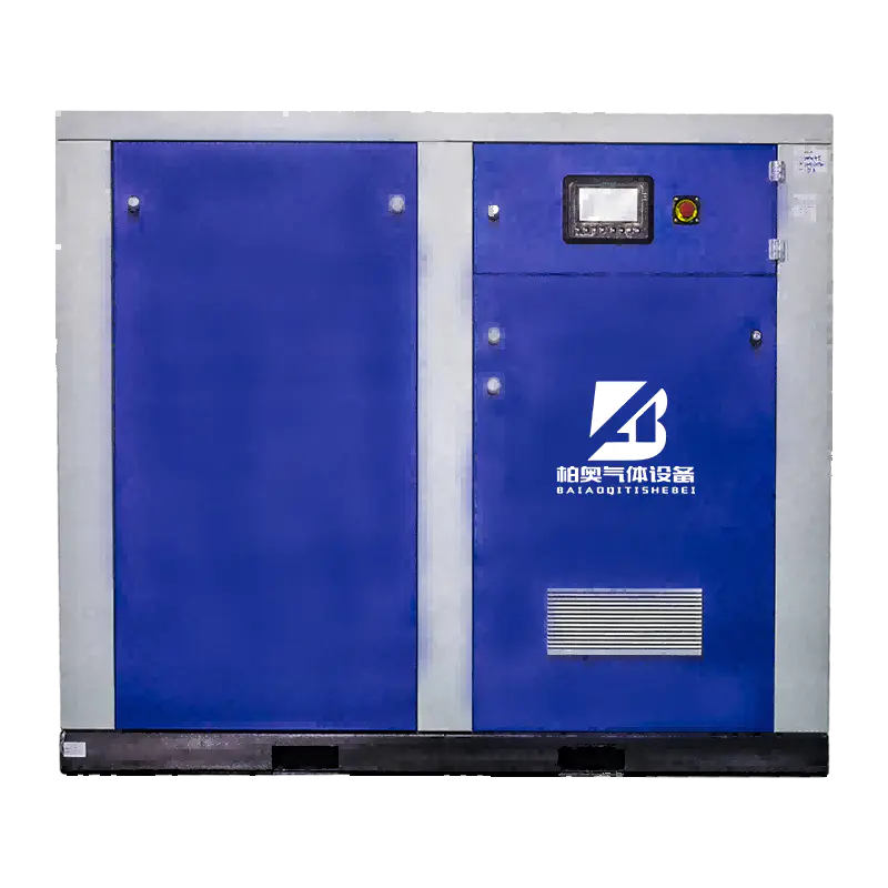
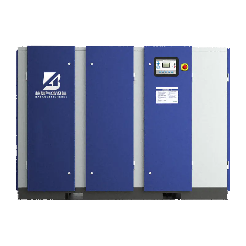
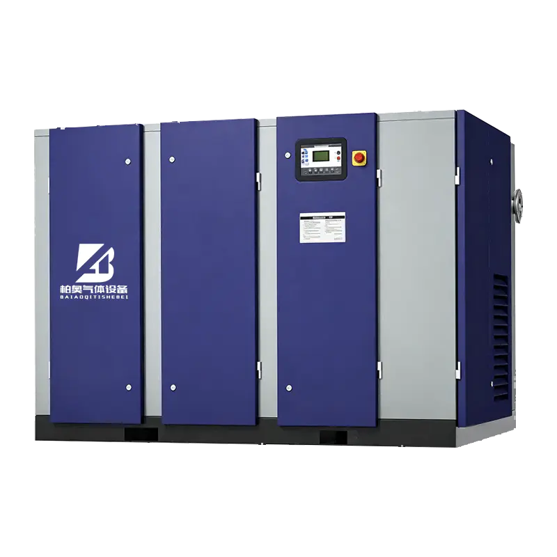
Medium-to-High Pressure Piston Air Compressor for Efficient Industrial Gas Applications
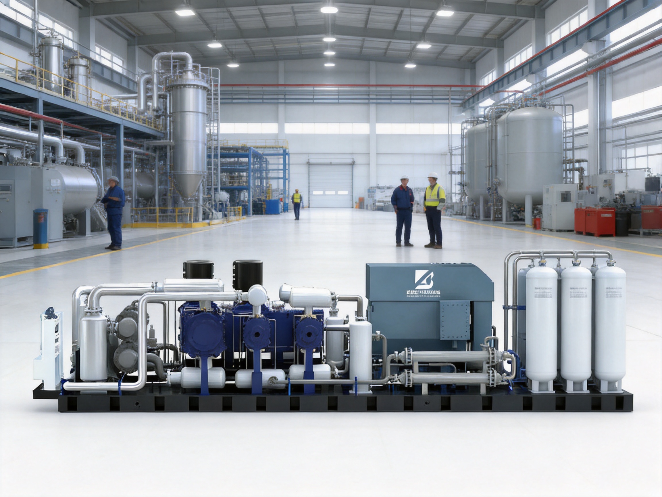
Medium-to-high pressure compressed air is essential in many industrial processes, including gas separation, gas purification, petrochemical production, heat treatment, automotive manufacturing, textile processing, food processing, and electronics assembly. These applications require more than simply generating compressed air. They require stable pressure, dependable air quality, efficient energy use, controlled operating temperature, low noise, and reliable performance over long operating periods.
The Medium-to-High Pressure Piston Air Compressor is designed for demanding industrial environments where ordinary low-pressure compressors cannot provide sufficient pressure or operating stability. With a working pressure range of 20 to 40 bar, air capacity from 1.6 to 37.7 cubic meters per minute, and motor power from 22 to 315 kW, the compressor serves a broad range of medium- and high-pressure applications.
Its design combines a durable two-stage integrated air end, third-generation asymmetric rotor technology, individually geared rotor stages, an IE3 motor, independent air intake, a centrifugal cooling fan, a high-pressure plate-fin cooler, a professional oil-gas vessel, and a specially designed oil supply system. Together, these features address the most common problems associated with medium-to-high pressure compression: high energy consumption, thermal stress, oil carryover, excessive noise, vibration, difficult starting, and shortened component life.
The equipment is manufactured by Zhejiang Baiao Gas Equipment Co., Ltd., a Chinese gas equipment manufacturer integrating research and development, engineering design, production, installation, and after-sales support. The company’s product portfolio includes gas separation and purification equipment, PSA nitrogen generators, PSA oxygen generators, membrane gas generators, nitrogen purification units, and ammonia decomposition hydrogen purification equipment. This broader technical background is important because compressed air is often the first stage in a complete industrial gas system.
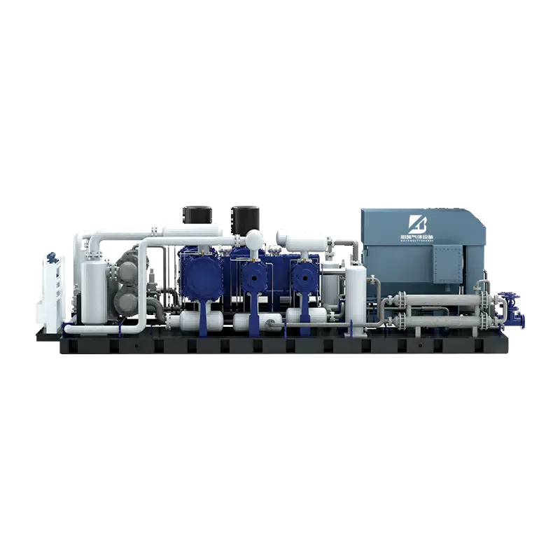
Medium-to-High Pressure Piston Air Compressor
Content
- 1 1. The Role of Medium-to-High Pressure Air Compression
- 2 2. Product Performance Range
- 3 3. Durable and Stable Air End Design
- 4 4. Heavy-Duty Bearings and Rotor Balance
- 5 5. IE3 Motor Efficiency and Industrial Protection
- 6 6. Multiple Noise Reduction Measures
- 7 7. Independent Air Intake and Improved Starting Performance
- 8 8. Centrifugal Fan and High-Pressure Plate-Fin Cooler
- 9 9. Professional Oil-Gas Vessel and Low Oil Carryover
- 10 10. Specially Designed Air End Oil Supply System
- 11 11. Advantages Compared with Conventional Alternatives
- 12 12. Manufacturing and Engineering Strengths
- 13 13. Installation Considerations
- 14 14. Operation and Maintenance
- 15 15. Selecting the Correct Model
- 16 16. Application in Gas Separation and Purification Systems
- 17 17. Application in Other Industrial Sectors
- 18 18. Total Cost of Ownership
- 19 19. Frequently Asked Questions
- 19.1 What pressure range does this compressor support?
- 19.2 What air capacity is available?
- 19.3 What motor power range is available?
- 19.4 Why is a two-stage air end useful for medium-to-high pressure service?
- 19.5 What is the advantage of individually geared rotor stages?
- 19.6 What does the IE3 motor provide?
- 19.7 How does the compressor reduce noise?
- 19.8 What is the purpose of the no-load starting intake valve group?
- 19.9 How is hot-air recirculation reduced?
- 19.10 What is the oil content of the compressed air?
- 19.11 Can this compressor be used with PSA nitrogen or oxygen generators?
- 19.12 What maintenance is required?
- 19.13 Is the compressor suitable for dusty environments?
- 19.14 What information should be provided when requesting a quotation?
- 20 20. Conclusion
- 21 References
- 22 Product: Medium-to-High Pressure Piston Air Compressor
1. The Role of Medium-to-High Pressure Air Compression
Compressed air is frequently described as an industrial utility, but in many production systems it is a process medium. The pressure and quality of the air can directly influence production efficiency, product quality, equipment safety, and operating costs. In a gas generation plant, for example, compressed air may be used to feed an adsorption system, operate pneumatic valves, support regeneration cycles, or provide the initial gas stream for purification.
When higher pressure is required, the compressor must operate under significantly greater mechanical and thermal loads. Increasing pressure is not simply a matter of selecting a larger motor. The air end, bearings, gears, oil circuit, cooling system, separator vessel, control components, and discharge piping must all be designed for the intended pressure range.
A compressor that performs acceptably at a lower pressure may become inefficient or unstable when used at 20 to 40 bar. Higher pressure can increase compression heat, place greater loads on bearings and rotors, increase oil circulation requirements, and intensify the effects of poor ventilation. For this reason, medium-to-high pressure systems require specialized equipment rather than a standard low-pressure unit operated outside its ideal range.
The compressor described in this article is intended for applications where a stable supply of compressed air is required at 20 to 40 bar. Its rated air capacity ranges from 1.6 to 37.7 m³/min, equivalent to approximately 56.5 to 1,331.4 cubic feet per minute. The available motor power range of 22 to 315 kW allows users to select a suitable configuration according to plant capacity, pressure requirements, and operating schedule.
Typical Industrial Applications
Medium-to-high pressure compressed air can support many industrial processes. In gas separation plants, it may be used as feed air for oxygen or nitrogen generation equipment. In gas purification systems, it can support adsorption, regeneration, valve actuation, and instrument air systems. In the petrochemical sector, reliable high-pressure air is often required for process control and equipment operation.
In the textile industry, stable compressed air is used for pneumatic control, air-jet machinery, and automated handling equipment. Food processing facilities use compressed air for packaging, conveying, automation, and cleaning systems, although suitable downstream treatment is required where air may contact products. Automotive manufacturing plants use compressed air in assembly, painting, testing, pneumatic tools, and component production.
Heat treatment operations may require compressed air for controlled atmospheres, pneumatic systems, or auxiliary process equipment. SMT electronics production depends on clean, stable air for pick-and-place machines, pneumatic actuators, soldering systems, and other automated equipment. Across these industries, compressor reliability is closely connected to production continuity.
2. Product Performance Range
The compressor is available in a practical range of operating specifications for industrial users. The main parameters are summarized below.
| Parameter | Metric Range | Imperial Range |
|---|---|---|
| Working pressure | 20–40 bar | 290.1–580.6 psig |
| Air capacity, FAD | 1.6–37.7 m³/min | 56.5–1,331.4 cfm |
| Motor power | 22–315 kW | 30.0–428.3 hp |
| Motor protection rating | IP54 | Suitable for industrial environments |
| Motor efficiency class | IE3 | High-efficiency industrial motor |
The capacity range allows the compressor to be used in both smaller process systems and larger industrial installations. The correct model should be selected according to actual free air delivery, required pressure, duty cycle, ambient temperature, altitude, cooling conditions, air quality requirements, and future expansion plans.
Free air delivery, or FAD, is particularly important when comparing compressors. It represents the delivered air converted to a reference condition, making it more useful for system planning than a simple outlet volume measurement. Users should review the manufacturer’s performance data at the actual working pressure rather than comparing nominal motor power alone.
3. Durable and Stable Air End Design
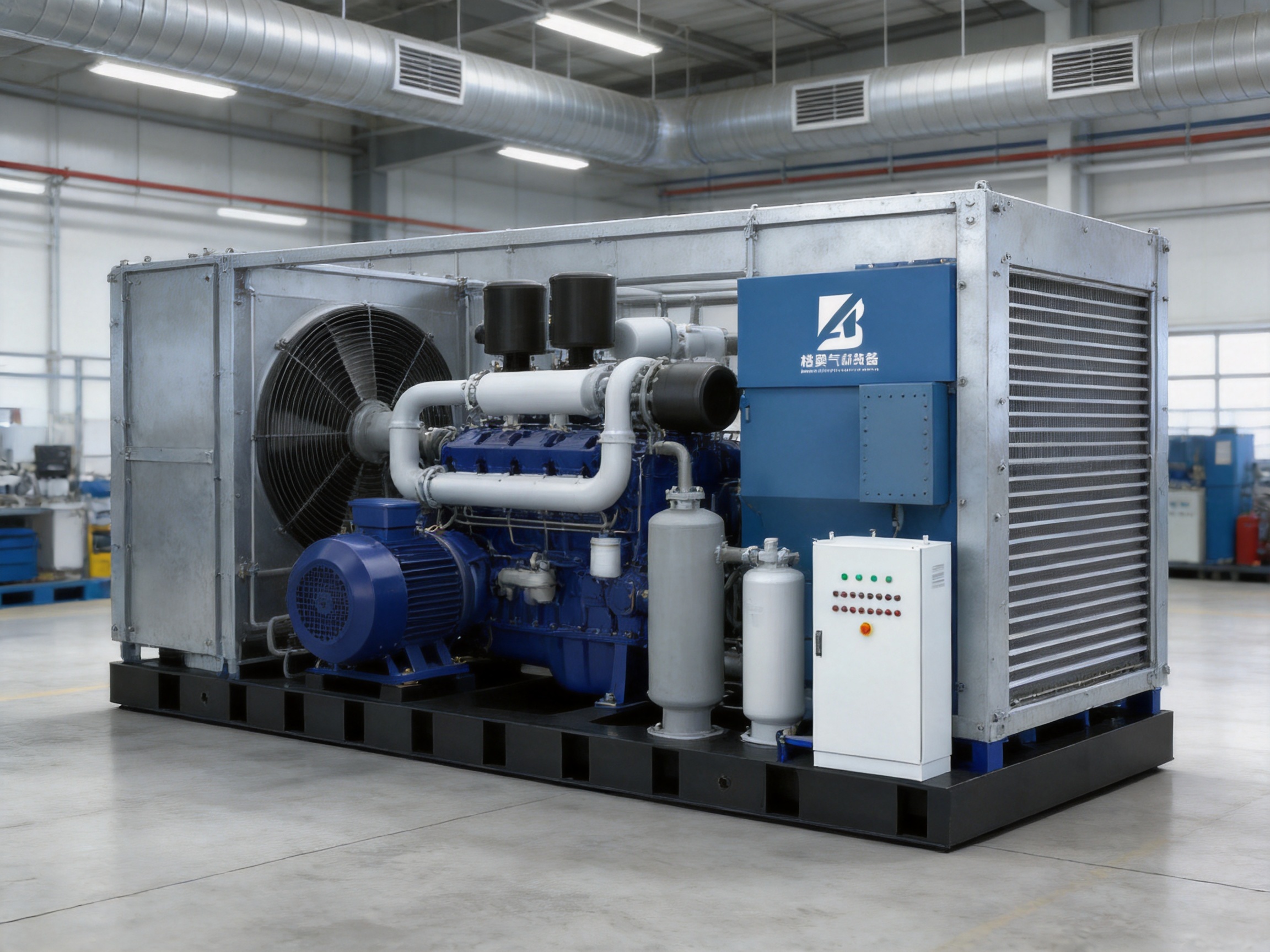
The air end is the central compression component. Its mechanical condition has a direct influence on energy consumption, pressure stability, noise, vibration, oil temperature, and service life. The compressor uses a two-stage integrated air end featuring third-generation asymmetric rotor technology. This design is tailored to the compression ratio requirements of medium-pressure operation and supports high volumetric efficiency.
Asymmetric rotor technology is intended to improve the way air is transported and compressed inside the air end. The rotor profile, clearances, timing, and compression geometry are coordinated to reduce unnecessary internal leakage and improve the utilization of the available swept volume. High volumetric efficiency means that more of the theoretical air-handling capacity is converted into useful delivered air.
For industrial users, improved volumetric efficiency can support lower specific energy consumption. It can also reduce the need to oversize the compressor to compensate for internal losses. Over a long operating period, even moderate efficiency improvements may have a meaningful effect on electricity costs, particularly in plants operating multiple shifts or continuously.
Two-Stage Compression for Pressure Matching
Achieving 20 to 40 bar requires a higher compression ratio than many general-purpose compressed-air systems. A two-stage arrangement divides the total pressure increase between two compression stages. This approach can help control discharge temperature, improve compression efficiency, and reduce the mechanical stress that would occur if the entire pressure increase were attempted in a single stage.
The two-stage air end is designed around the pressure ratio required for medium-to-high pressure service. Rather than treating high pressure as an afterthought, the system aligns the rotor design, gear transmission, oil supply, cooling, and separation system with the intended operating range.
Each rotor stage is individually driven by gears. This arrangement allows the stages to operate at their respective optimal linear speeds. Different rotor sizes and compression duties do not necessarily require the same rotational speed. Independent geared drive enables each stage to be matched more accurately to its operating function.
Compared with a system in which both stages are forced to operate at the same speed, individually driven stages can provide greater flexibility in optimizing compression performance. The result is a more balanced relationship among pressure ratio, rotor speed, air delivery, power consumption, and temperature control.
Large-Rotor, Low-Speed Operation
The air end uses a large-rotor, low-speed design. Larger rotors can move the required volume of air at a lower rotational speed, while lower speed generally helps reduce mechanical noise, vibration, and wear. This is especially valuable in a high-pressure compressor because high pressure already increases the load placed on bearings, gears, seals, and other components.
Low-speed operation may also contribute to smoother running. Reduced rotational speed can lessen dynamic forces and help the rotor assembly maintain stable operation under load. When combined with careful balancing and heavy-duty bearings, the design supports consistent operation during extended working periods.
Noise and vibration are not only matters of workplace comfort. Excessive vibration can loosen fasteners, stress pipe connections, damage auxiliary equipment, and accelerate bearing or seal deterioration. Lower mechanical vibration therefore contributes to both operator comfort and equipment reliability.
4. Heavy-Duty Bearings and Rotor Balance
Bearings are among the most important service components in a high-pressure air end. They must support rotating elements while resisting radial and axial loads generated during compression. If bearing loading is poorly managed, the compressor may experience increased vibration, temperature rise, lubricant deterioration, and premature failure.
The air end is equipped with heavy-duty bearings selected for the demands of industrial compression. The rotors are designed to remain exceptionally well balanced under load. This is important because a rotor that is acceptable under no-load conditions may behave differently once pressure forces are applied during operation.
Balanced rotor behavior helps reduce unnecessary dynamic forces. It can also support stable gear meshing and more uniform loading across the bearing system. When the air end operates smoothly, the cooling and lubrication systems can perform more consistently, and the risk of local hot spots or abnormal wear may be reduced.
For plant operators, the practical advantage is predictable operation. A compressor that maintains smooth rotation under changing load conditions is easier to integrate into an automated production system. It is also easier to maintain because abnormal sound, vibration, or temperature trends are less likely to be masked by normal mechanical instability.
5. IE3 Motor Efficiency and Industrial Protection
The compressor uses an IE3 high-efficiency motor. Motor efficiency is a major factor in the total cost of ownership of a compressor because the motor consumes electricity every time the unit operates. In many industrial plants, energy consumption represents a larger long-term expense than the initial purchase price.
An IE3 motor is designed to reduce electrical losses compared with lower-efficiency motor classes. Reduced losses can help lower operating costs and may also reduce the heat generated by the motor. Lower motor heat can support a more manageable thermal environment inside the compressor package, especially when the equipment operates for long periods.
The motor has an IP54 protection rating. This provides protection against harmful dust deposits and water splashing from different directions, making the motor suitable for many industrial environments. IP54 does not mean that the motor can be exposed to unlimited dust, flooding, or direct high-pressure water cleaning. Proper installation and routine maintenance remain essential.
The motor also features a Class B temperature rise. This indicates a controlled temperature-rise design that is suitable for demanding operating conditions when the compressor is installed and ventilated correctly. The combination of IE3 efficiency, IP54 protection, and Class B temperature rise makes the motor appropriate for industrial locations that may involve dust, heat, and extended operating hours.
Compared with an ordinary motor selected without considering ambient conditions, this motor specification offers a stronger foundation for reliable operation. Nevertheless, users should still provide adequate room ventilation, maintain cooling passages, prevent excessive dust accumulation, and confirm that site conditions fall within the approved operating limits.
6. Multiple Noise Reduction Measures
Noise is a common concern in compressor rooms and production areas. Medium-to-high pressure compression can produce sound from the air end, motor, gears, cooling fan, air intake, and exhaust flow. A compressor may meet its pressure requirement yet still create an uncomfortable or disruptive working environment if noise control is not considered during design.
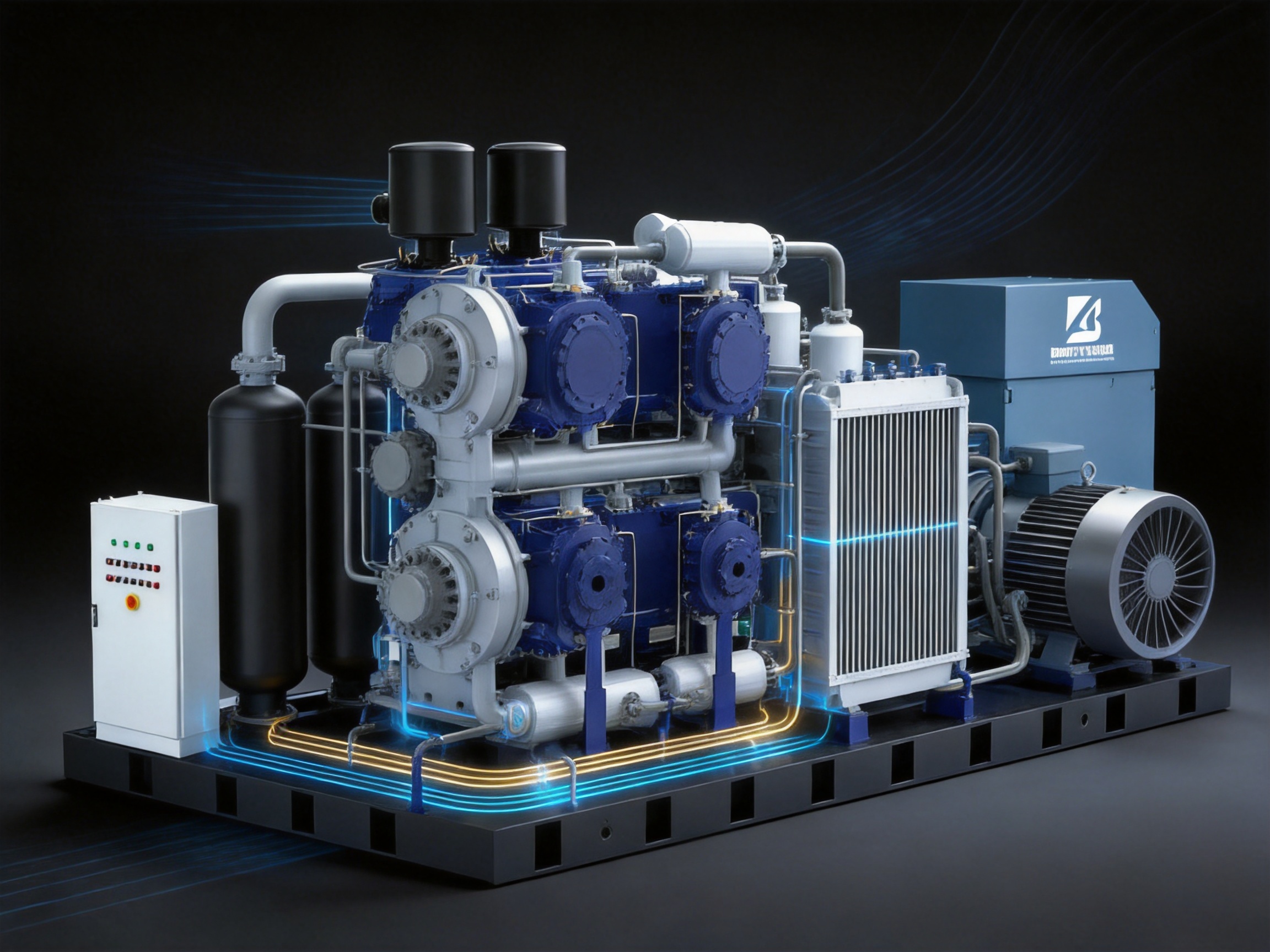
This compressor incorporates multiple noise reduction measures based on noise theory. The internal enclosure includes specially selected flame-retardant muffler cotton. The material is designed to absorb and reduce airborne sound while also meeting the safety requirements associated with industrial equipment enclosures.
Noise reduction is not limited to adding insulation after the compressor has been built. Effective acoustic performance depends on the coordination of several elements: the speed of rotating parts, rotor balance, airflow design, enclosure construction, intake treatment, exhaust duct routing, fan selection, and vibration isolation.
The large-rotor, low-speed air end contributes to lower mechanical noise and vibration. The centrifugal fan is designed to provide high wind pressure with low noise. Independent air intake and upward exhaust also help control the movement of hot air and high-velocity discharge flow around the machine.
A quieter compressor can improve the working environment for operators and maintenance staff. It may also reduce the need for a separate compressor room or extensive acoustic treatment, depending on local regulations and site conditions. Users should still conduct a project-specific noise assessment because actual sound levels depend on installation, room acoustics, distance, pipework, foundations, and operating load.
7. Independent Air Intake and Improved Starting Performance
The independent air intake system is designed to reduce intake resistance. Intake resistance directly affects compressor efficiency because the air end must draw air through filters, valves, ducts, and other restrictions. Excessive resistance can increase the power required for a given air delivery and may place unnecessary stress on the intake system.
The compressor uses a multifunctional intake valve group that supports no-load starting. Starting a high-power compressor under full compression load can create a substantial demand on the motor and electrical system. No-load starting reduces the initial mechanical and electrical burden, allowing the motor to accelerate more smoothly before the compressor is loaded.
This feature can help reduce starting current effects, improve starting stability, and reduce stress on couplings, gears, bearings, and other drive components. It may be especially useful in facilities where the electrical supply has limited short-term capacity or where multiple large motors start within the same period.
The intake system also uses high-efficiency filters to remove particulate matter from incoming air. Dust and suspended particles can damage internal components, contaminate lubricating oil, block cooler passages, and reduce separator performance. Effective filtration is therefore important for both air quality and mechanical protection.
Filter maintenance remains necessary. A filter that becomes heavily loaded with dust may create greater resistance than a clean filter, reducing efficiency and potentially affecting capacity. Operators should establish inspection and replacement intervals based on ambient conditions, operating hours, and differential-pressure indications where available.
8. Centrifugal Fan and High-Pressure Plate-Fin Cooler
Heat management is one of the most important challenges in medium-to-high pressure compression. Compression generates heat, and high operating pressure can increase the thermal load on the air end, oil circuit, motor, and separator system. If heat is not removed effectively, oil viscosity may change, seals may deteriorate, and the compressor may enter a protective shutdown condition.
The compressor uses a centrifugal fan with high wind pressure and low noise. The fan provides the airflow necessary to remove heat from the cooler and the compressor enclosure. High wind pressure helps maintain airflow through the cooler even when the installation has ducting, filters, or other resistance.
The cooling system has an independent external air intake. Heated air is exhausted upward through a specially designed air duct. This arrangement helps prevent hot-air recirculation, in which the cooling fan draws back air that has already passed through the cooler. Hot-air recirculation can gradually raise the intake temperature and reduce cooling effectiveness.
Upward discharge is also practical for many industrial installations because it directs heated air away from personnel and adjacent equipment. The installation should still provide sufficient clearance above the exhaust and should be designed to prevent the hot discharge air from entering nearby ventilation intakes.
Plate-Fin Cooler Advantages
The high-pressure plate-fin cooler provides high heat exchange efficiency with low internal pressure loss. Its structure offers a large heat-transfer area within a compact arrangement. Low internal pressure loss helps maintain the circulation performance of the oil system while minimizing unnecessary energy consumption by the cooling system.
The cooler is designed to allow the oil to exchange heat fully and evenly. This reduces the risk of localized hot zones, which may occur when fluid movement is uneven or when part of the heat-transfer surface is not effectively utilized. Eliminating hot zones supports more uniform oil temperature and helps protect lubrication performance.
Oil temperature should be monitored as part of routine operation. Even a well-designed cooler cannot compensate for blocked passages, excessive ambient temperature, inadequate ventilation, incorrect oil selection, or poor maintenance. Regular cleaning and inspection are essential to preserve the intended thermal performance.
9. Professional Oil-Gas Vessel and Low Oil Carryover
Oil management is critical in an oil-injected compressor. Oil lubricates moving components, helps seal internal clearances, and removes heat from the compression process. After compression, the oil must be separated from the compressed air before the air enters the plant system.
The compressor uses a professional oil-gas vessel developed specifically for medium-to-high pressure conditions. The vessel provides coarse separation across different operating states. Effective coarse separation reduces the quantity of oil reaching the secondary separation stage and supports the overall efficiency of the separation process.
After the initial separation, the compressed air passes through a customized oil separator core for secondary separation. According to the supplied product specification, the final oil content in the compressed air does not exceed 3 ppm under the stated operating conditions.
Low oil carryover is important for downstream equipment. Excessive oil can contaminate adsorption materials, reduce the performance of gas purification systems, damage pneumatic components, affect product quality, and increase maintenance requirements. In applications involving gas separation or purification, controlling oil carryover is especially important because downstream filters, dryers, and purification media may be sensitive to oil contamination.
The stated oil content should be evaluated together with the complete air treatment system. Actual air quality at the point of use depends on compressor operating conditions, separator condition, oil type, filter selection, condensate management, pipework cleanliness, and maintenance intervals. Where the compressed air is used for critical processing, users should specify the required air-quality class and verify performance through appropriate testing.
Why Separation Performance Matters in Gas Plants
Gas generation systems often involve multiple stages of treatment. A typical system may include compression, cooling, moisture separation, filtration, adsorption or membrane separation, purification, storage, and distribution. Oil entering the downstream equipment can reduce the effective service life of filters and adsorbents.
By combining coarse separation in the oil-gas vessel with secondary separation in the customized separator core, the compressor provides a stronger first line of defense against oil contamination. This design can reduce the load placed on downstream coalescing filters and help maintain more stable air quality over time.
10. Specially Designed Air End Oil Supply System
Lubrication reliability becomes increasingly important as a compressor operates for longer periods. Bearings and other internal components need a consistent supply of oil at suitable pressure and temperature. If oil supply declines during extended operation, the bearings may experience elevated friction, increased temperature, accelerated wear, and reduced service life.
The compressor includes a specially designed air end oil supply system that stabilizes oil supply pressure. The system is intended to ensure that the air end, particularly the bearings, receives adequate oil during long-term operation and in later stages of service life.
Stable oil supply supports more consistent lubrication under changing operating conditions. It also helps the compressor maintain reliable performance when the oil temperature changes, when the load varies, or when internal clearances develop gradually through normal service.
Oil supply design is a significant advantage over basic systems that rely on less controlled circulation. In a medium-to-high pressure compressor, lubrication must be treated as part of the overall pressure and thermal management system rather than as a separate auxiliary function.
Operators should use the specified lubricant, maintain the correct oil level, inspect oil filters, monitor oil temperature, and follow recommended replacement intervals. The use of an incorrect oil or a mixture of incompatible lubricants can affect viscosity, separation performance, sealing, and component life.
11. Advantages Compared with Conventional Alternatives
The compressor’s advantages become clearer when it is compared with conventional equipment that has not been specifically optimized for medium-to-high pressure duty. The comparison should not be understood as a universal claim that one machine is suitable for every application. Instead, it highlights the design considerations that may benefit users operating in demanding conditions.
Pressure-Specific Engineering
Conventional low-pressure compressors may require additional boosting stages, external modifications, or operation outside their most efficient range to achieve 20 to 40 bar. The equipment described here is designed around the pressure range from the beginning. Its two-stage air end, geared rotor stages, oil-gas vessel, oil supply system, and cooling package are coordinated for medium-to-high pressure service.
Energy Efficiency
The IE3 motor helps reduce electrical losses, while the asymmetric rotor profile and pressure-matched two-stage design support efficient compression. The independent intake reduces unnecessary suction resistance, and the plate-fin cooler reduces internal pressure loss. These features address energy use at several points rather than relying on motor efficiency alone.
Thermal Stability
High-pressure compression produces considerable heat. The centrifugal fan, independent external air intake, upward exhaust duct, and high-efficiency plate-fin cooler work together to improve heat removal and limit hot-air recirculation. A conventional system without these provisions may be more vulnerable to elevated oil and motor temperatures, especially in hot industrial environments.
Reduced Noise and Vibration
The large-rotor, low-speed design, balanced rotors, heavy-duty bearings, acoustic materials, and low-noise centrifugal fan help reduce operating noise and vibration. This can provide a better environment for operators and reduce mechanical stress on the compressor and connected piping.
Air Quality Protection
The high-efficiency intake filter protects the air end from particulate matter, while the professional oil-gas vessel and secondary separator core reduce oil carryover. These measures are particularly useful where compressed air is used in gas separation, purification, electronics, food processing, or other applications that require controlled air quality.
Long-Term Reliability
Durability depends on many coordinated design elements. Heavy-duty bearings, stable oil pressure, controlled operating temperature, no-load starting, and proper rotor speed all contribute to a more reliable operating platform. These features can reduce the likelihood of avoidable stress during starting, continuous operation, and changing production demand.
12. Manufacturing and Engineering Strengths
The manufacturer, Zhejiang Baiao Gas Equipment Co., Ltd., operates as an integrated gas equipment enterprise. Its activities include research and development, engineering design, production, installation, and after-sales service. This integrated structure is valuable for complex industrial equipment because performance depends not only on individual components but also on system integration.
The company operates a 3,000-square-meter standardized workshop, a 500-square-meter office area, and a 500-square-meter warehouse. These facilities support product assembly, engineering coordination, component storage, logistics, technical management, and customer service.
A standardized workshop can help organize production according to documented processes. For compressor manufacturing, important activities may include component inspection, air-end installation, motor and drive alignment, oil circuit assembly, cooler installation, electrical integration, enclosure assembly, testing, and final inspection.
Manufacturing quality is influenced by process discipline. Proper alignment of rotating components, accurate installation of seals, correct tightening of fasteners, clean oil lines, reliable electrical connections, and effective inspection procedures are all important. A standardized production environment helps reduce variation between units and supports repeatable assembly quality.
Technical Integration with Gas Equipment
The company specializes in gas separation and purification equipment, including PSA nitrogen generators, PSA oxygen generators, membrane nitrogen and oxygen generators, QH and QC series nitrogen purification units, and ammonia decomposition hydrogen purification units. This product background gives the company experience with the wider needs of industrial gas systems.
A compressor supplier that understands gas separation and purification can better appreciate the importance of pressure stability, air cleanliness, oil control, flow matching, and system coordination. The compressor may be used as an independent machine, but it can also form part of a complete gas generation or purification project.
System integration may include compressor selection, receiver sizing, filtration, drying, pressure regulation, piping design, control logic, gas generator matching, installation, commissioning, and operator training. Coordinating these elements helps reduce the risk of mismatched equipment and unstable operation.
Research, Development, and Product Optimization
The manufacturer develops products using overseas technologies while optimizing them for industrial conditions in China. This approach combines reference to established international design concepts with adaptation to practical operating environments, including dust, temperature variation, long duty cycles, and diverse industrial applications.
Product optimization may involve improving rotor profiles, cooling arrangements, separator design, motor selection, intake valves, control systems, or maintenance access. The objective is not simply to copy a technical solution but to adapt it to actual customer requirements and local operating conditions.
Quality and Service Orientation
The company emphasizes technical improvement, strict quality control, integrity, energy efficiency, and reliable service. These principles are relevant to industrial compressor users because equipment performance must be maintained after delivery. Installation, commissioning, maintenance guidance, spare-parts support, and troubleshooting all influence the real value of the compressor.
The company’s sales network covers more than 30 provinces and cities in China, and its products are also exported to international markets. Experience serving different regions can help the manufacturer understand variations in climate, electrical systems, plant standards, project documentation, and customer expectations.
13. Installation Considerations
Correct installation is essential for achieving the intended performance of the compressor. The equipment should be installed on a stable foundation capable of supporting its operating weight and dynamic loads. The foundation should be level, and vibration isolation should be evaluated according to the installation environment.
The compressor room should provide sufficient clearance for air circulation, inspection, filter replacement, oil service, separator replacement, and cooler cleaning. The independent air intake should not draw air from a location contaminated by dust, corrosive gases, exhaust fumes, or excessive moisture.
The cooling system requires careful attention. The external air intake should remain unobstructed, and the upward hot-air exhaust should be routed so that discharged heat does not return to the compressor room or enter other equipment. In hot climates, the design of room ventilation may need to include mechanical extraction or ducting.
Electrical installation should comply with applicable local standards. The power supply must match the motor specification, and protection devices should be selected according to the rated current, starting characteristics, and site conditions. Grounding, cable sizing, isolation, and emergency shutdown provisions should be completed by qualified personnel.
Compressed-air piping should be sized to avoid excessive pressure drop. The pipe system should include appropriate isolation valves, condensate management, downstream filtration, and maintenance provisions. Sudden changes in pipe diameter, unnecessary elbows, and undersized hoses can reduce system performance even when the compressor itself is operating correctly.
14. Operation and Maintenance
Routine maintenance is necessary to preserve efficiency and reliability. Operators should monitor working pressure, discharge temperature, oil temperature, motor current, vibration, noise, and separator performance. Changes in these values may indicate filter blockage, cooler fouling, oil deterioration, bearing wear, abnormal loading, or air leakage.
The intake filter should be inspected regularly, especially in dusty environments. A blocked filter increases intake resistance and may reduce air capacity. The cooler should be cleaned according to site conditions because dust and oil deposits reduce heat-transfer efficiency.
Oil level and oil condition should be checked using the manufacturer’s recommended procedures. Oil replacement intervals should be based on operating hours, temperature, contamination, and the approved lubricant specification. The oil separator and oil filters should be replaced when required rather than being used beyond their effective service life.
Any unusual vibration or sound should be investigated promptly. Early detection can prevent a minor issue from becoming a major failure. Maintenance personnel should inspect couplings, gears, bearings, fasteners, piping connections, fan operation, and mounting points when abnormal behavior is observed.
Before maintenance, the compressor must be isolated from electrical power and compressed-air pressure. Internal pressure should be fully released, and appropriate lockout and tagging procedures should be followed. High-pressure equipment requires disciplined safety practices during inspection and service.
15. Selecting the Correct Model
Model selection should begin with the required working pressure and actual free air delivery. Users should not select a compressor solely by motor power because two machines with similar motor ratings may provide different air capacities at the required pressure.
The duty cycle is also important. A compressor operating continuously at a stable load may require a different configuration from a compressor operating intermittently with frequent starts and stops. The number of operating shifts, annual working hours, production expansion plans, and standby requirements should all be considered.
Ambient conditions influence cooling and motor performance. Users should provide information about ambient temperature, altitude, humidity, dust, corrosive substances, and installation-room ventilation. These factors may affect the final configuration and allowable operating range.
Air quality requirements should be identified before the compressor is ordered. If the compressed air will feed a gas generator, purification unit, food process, electronics line, or other sensitive application, the complete treatment chain should be specified. This may include aftercoolers, water separators, coalescing filters, activated-carbon filters, dryers, and sterile or process-specific filtration.
Users should also consider the required control method, receiver volume, downstream pressure fluctuation, backup capacity, remote monitoring, and maintenance access. A technically suitable compressor can perform poorly if the surrounding system is undersized or incorrectly configured.
16. Application in Gas Separation and Purification Systems
The compressor is particularly relevant to gas separation and purification projects because compressed air is commonly used as the feed source for nitrogen and oxygen generation systems. PSA systems depend on stable feed conditions to achieve predictable adsorption and regeneration cycles. Pressure fluctuations, oil contamination, excessive moisture, or inadequate flow can affect gas production and purity.
In a nitrogen generation system, compressed air may pass through cooling, filtration, drying, and adsorption before nitrogen is separated from oxygen and other components. The compressor’s low oil carryover and stable pressure characteristics can support the protection of downstream equipment, although the complete system must still include suitable air treatment.
Oxygen generation systems also require reliable feed air. The compressor must be selected in accordance with the oxygen generator’s required pressure, flow, purity, and operating cycle. The compressor should not be treated as an isolated component; its performance must be matched to the adsorption vessel volume, valve timing, storage capacity, and oxygen demand.
Membrane nitrogen and oxygen systems may also benefit from stable compressed-air supply. Membrane separation performance is influenced by pressure, temperature, flow rate, and feed-air quality. A compressor with controlled pressure and effective cooling can provide a more consistent feed source for membrane modules.
Purification systems, including nitrogen purification and hydrogen purification equipment, may require compressed air for control systems, regeneration, or upstream processing. The manufacturer’s experience with gas purification equipment enables the compressor to be considered within a broader plant design rather than only as a standalone utility.
17. Application in Other Industrial Sectors
In petrochemical plants, compressed air supports pneumatic control valves, instrumentation, process equipment, and maintenance operations. Stable pressure and low oil carryover are important because contaminated instrument air can affect valve operation and control reliability.
In textile production, compressed air may support high-speed pneumatic machinery and air-jet equipment. Production interruptions can result in material waste and reduced output, so compressor stability is important. Low noise can also be beneficial in facilities where personnel work near the equipment.
Food-processing plants require special attention to hygiene and air quality. Where compressed air may contact food or packaging surfaces, appropriate filtration and treatment must be added in accordance with applicable standards. The compressor’s oil separation performance provides a useful foundation, but the final air system must be designed for the specific food application.
Automotive manufacturing uses compressed air for assembly, painting, testing, robotics, pneumatic tools, and material handling. These processes may have different pressure and air-quality requirements, so a centralized compressor system may use several treatment branches to meet individual points of use.
Heat-treatment facilities often operate in hot environments. The compressor’s cooling design, motor protection, and high-pressure air end can be advantageous, but ventilation and ambient-temperature limits must be respected. In electronics and SMT production, clean and stable compressed air helps protect precision pneumatic components and automated equipment.
18. Total Cost of Ownership
The purchase price is only one part of compressor economics. Total cost of ownership includes electricity, maintenance, lubricant, filters, separator elements, cooling-system cleaning, downtime, spare parts, and eventual replacement. A design that reduces energy consumption and extends service intervals may provide greater value over the full operating life.
The IE3 motor directly supports energy efficiency. The pressure-matched two-stage air end, asymmetric rotor technology, low-resistance intake, and efficient cooler also contribute to lower operating losses. These features should be evaluated using actual performance data at the required pressure and flow.
Reliability also affects cost. Unexpected shutdowns can interrupt production, affect downstream gas generation, cause product losses, and require urgent service. Heavy-duty bearings, balanced rotors, stable oil supply, and effective thermal control are intended to reduce the risk of avoidable failures.
Maintenance access and service planning should be considered during equipment selection. Filters, oil, separator cores, and cooler surfaces require regular attention. A clear maintenance schedule helps prevent gradual efficiency loss and protects the compressor from operating in abnormal conditions.
19. Frequently Asked Questions
What pressure range does this compressor support?
The stated working pressure range is 20 to 40 bar, equivalent to approximately 290.1 to 580.6 psig. The final operating pressure should be selected according to the model configuration and application requirements.
What air capacity is available?
The available free air delivery range is 1.6 to 37.7 m³/min, or approximately 56.5 to 1,331.4 cfm. Actual capacity depends on the selected model, working pressure, ambient conditions, and operating state.
What motor power range is available?
The compressor is available with motor power from 22 to 315 kW, equivalent to approximately 30.0 to 428.3 horsepower.
Why is a two-stage air end useful for medium-to-high pressure service?
A two-stage air end divides the total compression ratio between two stages. This can improve pressure-ratio matching, manage compression heat, reduce stress on individual stages, and support efficient operation at higher pressures.
What is the advantage of individually geared rotor stages?
Individually geared stages can operate at different rotational speeds suited to their respective rotor sizes and compression duties. This helps each stage operate closer to its optimal linear speed.
What does the IE3 motor provide?
The IE3 motor is designed for improved energy efficiency compared with lower-efficiency motor classes. It also has IP54 protection and Class B temperature rise, making it suitable for many industrial environments when correctly installed and maintained.
How does the compressor reduce noise?
Noise reduction comes from several design elements, including the large-rotor, low-speed air end, balanced rotors, heavy-duty bearings, specially selected internal muffler cotton, and a low-noise centrifugal fan.
What is the purpose of the no-load starting intake valve group?
The multifunctional intake valve group reduces the load on the motor during startup. This allows the motor to accelerate more smoothly before the compressor begins full-load compression.
How is hot-air recirculation reduced?
The cooling system uses an independent external air intake and directs heated air upward through a specially designed air duct. This arrangement helps prevent the fan from drawing back air that has already been heated by the cooler.
What is the oil content of the compressed air?
According to the supplied specification, final oil content does not exceed 3 ppm after coarse separation in the oil-gas vessel and secondary separation through the customized oil separator core. Actual point-of-use air quality also depends on downstream treatment and maintenance.
Can this compressor be used with PSA nitrogen or oxygen generators?
Yes, it is suitable for consideration as a compressed-air source for gas separation and purification systems, including PSA applications. The selected model must be matched to the generator’s required flow, pressure, air quality, and operating cycle.
What maintenance is required?
Typical maintenance includes inspection and replacement of intake filters, oil filters, separator elements, and lubricant; cleaning of the cooler; checking oil temperature and pressure; inspecting vibration and noise; and verifying electrical and safety systems. Exact intervals should follow the manufacturer’s service instructions and site conditions.
Is the compressor suitable for dusty environments?
The IP54 motor and high-efficiency intake filtration support operation in many industrial environments with dust. However, the compressor room must still be properly ventilated, and filters and cooler surfaces must be maintained according to the actual dust load.
What information should be provided when requesting a quotation?
Users should provide required pressure, free air delivery, duty cycle, ambient temperature, altitude, electrical supply, air-quality requirements, installation conditions, operating schedule, and whether the compressor will be integrated with a gas separation or purification system.
20. Conclusion
The Medium-to-High Pressure Piston Air Compressor is engineered for industrial users that require reliable compression at 20 to 40 bar. Its two-stage integrated air end, asymmetric rotor technology, individually geared rotor stages, balanced rotors, and heavy-duty bearings provide a stable mechanical foundation for demanding operation.
The IE3 motor supports energy-conscious operation, while IP54 protection and Class B temperature rise make the motor suitable for many challenging industrial environments. Independent air intake, no-load starting, high-efficiency filtration, centrifugal cooling, upward hot-air exhaust, and a high-pressure plate-fin cooler address the practical requirements of continuous industrial service.
The professional oil-gas vessel and customized secondary separator core help limit oil carryover to no more than 3 ppm under the stated conditions. The specially designed oil supply system supports stable lubrication pressure and helps protect bearings during long-term operation. These features are particularly valuable when the compressor supplies gas separation, gas purification, electronics, food-processing, or other applications where air quality and reliability are important.
The manufacturer’s broader experience in gas separation and purification equipment adds value for customers seeking more than a standalone compressor. Through research and development, standardized manufacturing, system design, installation, and after-sales service, the company is positioned to support complete industrial gas projects as well as individual compressed-air requirements.
For the best result, users should select the compressor according to actual flow, pressure, duty cycle, ambient conditions, air-quality requirements, and downstream equipment. When properly selected, installed, and maintained, this medium-to-high pressure compressor can provide a dependable foundation for efficient industrial production and gas processing.
References
1. Product technical information for the Medium-to-High Pressure Piston Air Compressor, including pressure, capacity, motor power, air-end design, cooling system, oil separation, and lubrication features.
2. International Electrotechnical Commission. Rotating Electrical Machines: Efficiency Classification and Motor Performance Principles.
3. International Electrotechnical Commission. Degrees of Protection Provided by Enclosures for Electrical Equipment.
4. Compressed Air and Gas Institute. Industrial Compressed-Air System Design and Performance Practices.
5. General engineering principles for two-stage compression, rotor balancing, bearing load management, oil separation, and industrial cooling systems.
6. Industrial gas engineering practices for PSA nitrogen generation, PSA oxygen generation, membrane separation, and gas purification system integration.
Product: Medium-to-High Pressure Piston Air Compressor

- Tel: +86-15057127179
+86-13588382771 - Email: huang.yifan0215@gmail.com
- Address: Huanshan Township, Fuyang District, Hangzhou City, Zhejiang Province
Copyright © Zhejiang Baiao Gas Equipment Co., Ltd. All Rights Reserved.
Privacy
Gas Generator Plant Manufacturer, Industrial Purification Equipment Plant
